Motion Picture Restoration
- Home /
- Research Highlights /
- Line Scratch Restoration /
- The color model
Color Scratches
by V. Bruni, P. Ferrara and D. Vitulano
- a scratch is caused by light diffraction: it is produced by the projector
light that passes through the slit (i.e. the damaged region) of the film
material.

Therefore,
- the scratch appears as an area of partially missing data , where the original information has not been completely removed
- the scratch profile on the luminance cross-section is
well-modelled by a sinc2 whose equation is:

where y is the horizontal abscissa (column number), cp and bp are respectively the column position and brightness of the scratch on the cross-section, and mp is the line width
Thus the model is

where I is the degraded image signal and G the original image one (see BW model)
COLOR FILM is based on the subtractive synthesis:
it filters colors from white light through three separate layers of sensitive emulsions that are respectively sensitive to blue, green and red
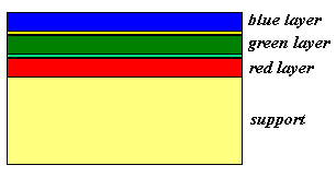
and the printed images are obtained using the subtractive color synthesis, i.e. yellow, magenta and cyan.
Hence,


The range of width of color scratches differs from the BW model because of the change of resolution and the diffraction effect.
In correspondence to blue scratches, blue light (i.e. wavelength l ~ .4 m m) is not absorbed. For red scratches ( l ~ .7 m m) it is the opposite, since the filter has been removed from the mechanism causing the scratch.
For that reason, the maximum width allowed for blue scratches, in the pure case, is about half of the maximum width allowed for red scratches.
The Algorithm
- Apply the BW
detection algorithm on the Magenta component (downsampled by 4) of the
CMYK color space using the diffraction model for the degradation (white
scratches are searched!)
Let C the set of candidates. For each element cp of C:
- Select the color component (among R,G,B) whose cross section has the highest value in correspondence to cp;
- compute the undecimated wavelet decomposition of the selected component;
- restore the wavelet low pass A and vertical detail bands V by attenuating scratch contribution under the local visibility threshold using the model equation
- Invert the wavelet decomposition using the restored bands and let Ip be the resulting partially restored image;
- extract the luminance component of Ip and evaluate the energy value in correspondence to cp in the cross section of this component, as done at step 5 of the detection algorithm. If the scratch is still visible, go to step 1 only considering the remaining color components.
Experimental Results


